Motek Module
Motek Medical sells hardware/software packages which include treadmills with force plate measurement capabilities and motion bases, motion capture systems, visual displays, and other sensors for various measurements. Their software, D-Flow, manages the data streams from the various systems and is responsible for displaying interactive visuals, sounds, and motions to the subject. The gaitanalysis.motek module includes classes that eases processing the data collected from typical D-Flow output files, but may have some limitations with respect to the hardware because we only have one system available.
The Human Motion and Control Lab at Cleveland State University has such a system. Our system includes:
- A ForceLink R-Mill which has dual 6 DoF force plates, independent belts for each foot, and lateral and pitch motion capabilities.
- A 10 Camera Motion Analysis motion capture system which includes the Cortex software and hardware for collecting analog and camera data simultaneously.
- Delsys wireless EMG + 3D Accelerometers.
- Motek Medical’s D-Flow software and visual display system.
Cortex alone is capable of delivering data from the cameras, force plates, and analog sensors (EMG/Accelerometer), but D-Flow is required to collect data from digital sensors and the treadmill’s motion (lateral, pitch, and belts). D-Flow can output multiple types of files which contain the different data.
Our motion capture system’s coordinate system is such that the X coordinate points to the right, the Y coordinate points upwards, and the Z coordinate follows from the right-hand-rule, i.e. points backwards with respect to a person walking forward on the treadmill. The camera’s coordinate system is aligned to an origin point on treadmill’s surface during camera calibration.
Mocap Module
D-Flow’s mocap module has a file tab which allows you to export the time series data collected from Cortex in two different file formats: tab separated values (TSV) and the C3D format (see http://www.c3d.org). The TSV files are approximately twice the size of the C3D files, don’t maintain machine precision, and do not allow for meta data storage. But for now, this software only deals with the TSV file format.
The text file output from the mocap module in DFlow is a tab delimited file. The first line is the header and contains a time stamp column, frame number column, marker position columns, force plate force/moment columns, force plate center of pressure columns, other analog columns, and potentially results from the real time Human Body Model which is included with the D-Flow software. These are detailed below. The numerical values of the measurements are provided in decimal floating point notation with 6 decimals of precision, e.g. 123456.123456 [%1.6f].
Data Column Descriptions
- Time Stamp
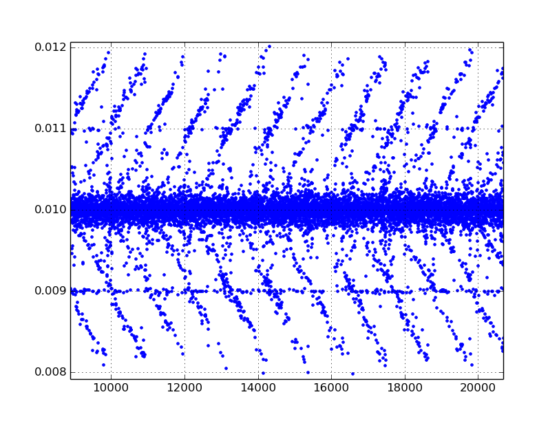
The TimeStamp column records the D-Flow system time when it receives a “frame” from Cortex in seconds since D-Flow was started. This is approximately at 100 hz (Cortex’s sample rate), but has slight variability per sample period, something like +/- 0.002 s or so. This column can be used to synchronize with other D-Flow output files which include a D-Flow time stamp, e.g. the output of the record module. The following figure shows the difference, .diff(), of an example D-Flow time stamp, giving the variability in periods at each measurement instance.
- Frame Number
- The FrameNumber column gives a positive integer to count the frame numbers delivered by Cortex. It seems as though none of the frames are ever dropped but this should be verified.
- Marker Coordinates
- The columns that correspond to marker coordinates have one of three suffixes: .PosX, .PosY, .PosZ. The prefix is the marker name which is set by providing a name to the marker in Cortex. There are specific names which are required for D-Flow’s Human Body Model’s computations. The marker coordinates are given in meters. See below for some additional virtual markers.
- Force Plate Kinetics
- There are three forces and three moments recorded by each of the two force plates in Newtons and Newton-Meters, respectively. The prefix for these columns is either FP1 or FP2 and represents either force plate 1 (left) or 2 (right). The suffixes are either .For[XYZ], .Mom[XYZ] for the forces and moments, respectively. The force plate voltages are sampled at a much higher frequency than the cameras, but delivered at the Cortex camera sample rate, 100 Hz through the D-Flow mocap module. A force/moment calibration matrix stored in Cortex converts the voltages to forces and moments before sending it to D-Flow [1]. Cortex also computes the center of pressure from the forces, moments, and force plate dimensions. These have the same prefixes for the plate number, have the suffix .Cop[XYZ], and are in meters.
- Analog Channels
Cortex can sample additional analog channels. These columns have headers which take this form Channel[1-99].Anlg and the names are fixed to correspond to the channels in the National Instruments DAQ box which samples the analog sensors. The first twelve of these are reserved for the force plate voltage measurements. These correspond to the voltages of the force sensors in the two force plates and are as follows (channels 1-12).
- F1Y1
- F1Y2
- F1Y3
- F1X1
- F1X2
- F1Z1
- F2Y1
- F2Y2
- F2Y3
- F2X1
- F2X2
- F2Z1
Top View of treadmill surface showing location of the Y sensors:
----------------------------
|    FP1     |     FP2     |
|            |             |
|         Y2 | Y2          |
|            |             |
|            |             |
| Y1         |          Y3 |    ----> X
|            |             |    |
|            |             |    V
|         Y3 | Y1          |    Z
|            |             |
----------------------------
The remaining analog channels are connected to the 16 Delsys EMG/Accelerometers measurements. Each sensor has four signals: EMG, AccX, AccY, and AccZ. The are ordered in the remaining channels as:
- EMG1
- ACCX1
- ACCY1
- ACCZ1
- EMG2
- ACCX2
- ACCY2
- ACCZ2
- etc.
Note that all of the signals are in volts!. You must scale them yourself.
Note
The EMG/Acceleromter channels are 96 milliseconds behind the force plate measurements, according to the DelSys manual [2]. There may be other delays present too that may or may not be taken care of in Cortex or D-Flow. The lag of the EMG/Accelerometers is due to the wireless communication.
- Human Body Model
- The mocap TSV file can also contain joint angles [degrees], joint moments [Newton-Meters], joint power [Watts], and muscle forces [Newtons] computed by the real time Human Body model. The joint angle headers end in .Ang, the joint moments in .Mom, the joint power .Pow, and the muscle forces are prefixed with R_ or L_. D-Flow also outputs the centor of mass in meters of the person in the HBM.COM.[XYZ] columns.
- Segment Positions and Rotations
D-Flow also outputs positional and rotational information about body segments. There are virtual markers with suffixes .Pos[XYZ] And there are also segment rotations in degrees. These header labels end in .Rot[XYZ]. The definition of the positions and rotations is unclear and it is unclear what they are used for. The following list gives the prefixes:
- pelvis
- thorax
- spine
- pelvislegs
- lfemur
- ltibia
- lfoot
- toes
- rfemur
- rtibia
- rfoot
- rtoes
Todo
There are probably more of these for the upper body.
| [1] | Cortex currently does not output anything for the .MomY momemt on both of the force plates. So D-Flow records the raw voltages from Cortex and applies the calibration matrix in D-Flow to get correct values using an .idc file. |
| [2] | We’ve done independent measurements that show a ~72 millisecond delay. |
Missing Values
D-Flow handles missing values internally to perform well with their real time computations, but there are some important issues to note when dealing with the data outputs from D-Flow with regards to missing values. Depending on how many markers were used, where they were placed, and what analysis is used, different techniques can be used to fill in the gaps.
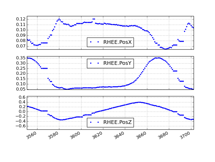
Firstly, the markers sometimes go missing (i.e. can’t been seen by the cameras) which is typical of motion capture systems. Care must be taken that all markers are always captured by the system, but there will always be some missing values. If the data was recorded in a D-Flow version less than 3.16.2rc4 [3], D-Flow records the last non-missing value in all three axes until the marker is visible again when a marker goes missing. The following figure gives an example:
| [3] | We received versions 3.16.1 and then 3.16.2rc4 so I have no idea when the change was introduced between those versions. If this software is used with a version between 3.16.1 and 3.16.2c4, then it may or may not work correctly. |
In D-Flow versions greater than or equal to 3.16.2rc4 the missing markers are indicated in the TSV file as either 0.000000 or -0.000000, which is the same as has been in the HBM columns in all versions of D-Flow. The D-Flow version must be provided in the meta data yml file, otherwise it will assume D-Flow is at the latest version.
The mocap output file can also contain variables computed by the real time implementation of the Human Body Model (HBM). If the HBM computation fails at a D-Flow sample period, strings of zeros, either 0.000000 or -0.000000, are inserted for missing values. The following figure shows the resulting HBM output with zeros:
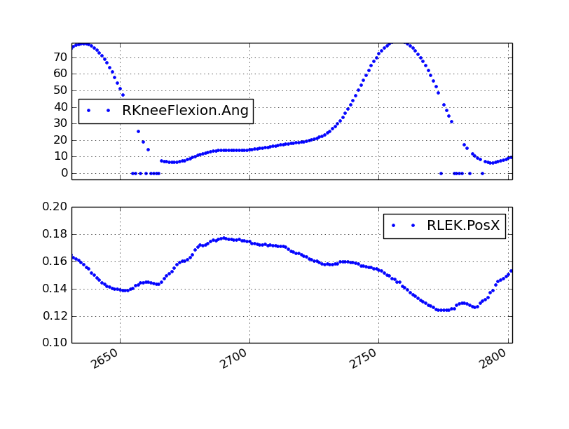
Notice that failed HBM computations don’t always correspond to missing markers.
The HBM software only handles zero values for marker coordinates. If markers are zero, then HBM ignores them and tries to compute the inverse dynamics with a reduced set of markers. So if you playback recordings which have missing markers stored as constant values in D-Flow, you will likely get incorrect inverse dynamics.
Time Delays
There are time delays between the camera marker data, force plate analog signals, and the wireless EMG/Accelerometers. The documentation for the Delsys wireless system explicity states that there is a 96ms delay in the data with respect to the analog signals that are sampled from the unit which is due to the wireless data transfer. There is also an measurable delay in the camera data with respect to the analog data which seems to hover around 7 ms.
Other
Note that the order of the “essential” measurements in the file must be retained if you expect to run the file back into D-Flow for playback. I think the essential measurements are the time stamp, frame number, marker coordinates, and force plate kinetics, and analog channels [4] (maybe because of the IDC file).
| [4] | The first twelve analog channels may only be required because we use the .idc file to work around the fact that the .MomY force plate moments are not correctly collected by D-Flow from Cortex. |
Inertial Compensation
If you accelerate the treadmill there will be forces and moments measured by the force plates that simply come from the inertial effects of the motion. When external loads are applied to the force plates, you must subtract these inertial forces from the measured forces to get correct estimates of the body fixed externally applied forces.
The markers are measured with respect to the camera’s inertial reference frame, earth, but the treadmill forces are measured with respect to the treadmill’s laterally and rotationally moving reference frame. We need both to be expressed in the same inertial reference frame for ease of future computations.
To deal with this we measure the location of additional markers affixed to the treadmill and the 3D acceleration of the treadmill at 4 points.
Typically, the additional accelerometers are connected to these channels and the arrow on the accelerometers which aligns with the local X axis direction is always pointing forward (i.e. aligned with the negative z direction).
# Front left
Channel13.Anlg : EMG
Channel14.Anlg : AccX
Channel15.Anlg : AccY
Channel16.Anlg : AccZ

# Back left
Channel17.Anlg : EMG
Channel18.Anlg : AccX
Channel19.Anlg : AccY
Channel20.Anlg : AccZ

# Front right
Channel21.Anlg : EMG
Channel22.Anlg : AccX
Channel23.Anlg : AccY
Channel24.Anlg : AccZ

# Back right
Channel25.Anlg : EMG
Channel26.Anlg : AccX
Channel27.Anlg : AccY
Channel28.Anlg : AccZ
This information will be stored in the meta data file, see below.
Location of of accels and markers should stay the same between unloaded and loaded trials, but position doesn’t matter other wise.
Record Module
The record module in D-Flow allows one to sample any signal available in the D-Flow environment at the variable D-Flow sample rate which can vary from 0 to 300 Hz depending on how fast D-Flow is completing it’s computations. Any signal that you desire to record, including the ones already provided in the Mocap Module, are available. This is particularly useful for measuring the motions of the treadmill: both belts’ speed, lateral motion, and pitching motion. The record module only outputs a tab delimited text file. It includes a Time column which records the D-Flow system time in seconds which corresponds to the same time recorded in the TimeStamp column in mocap module tsv file. And it additionally records the 6 decimal precision values of other measurements that you include. Finally, the record module is capable of recording the time at which various D-Flow events occur. It does this by inserting commented (#) lines in between the rows when the event occurred. For example an event may look like:
#
# EVENT A - COUNT 1
#
Where A is the event name (fixed by D-Flow, you can’t select custom names) and the number after COUNT gives an integer count of how many times that event has occurred. D-Flow only seems to allow a total of 6 unique events to be recorded, with names A-F. At the end of the file the total number of event occurrences are counted:
# EVENT A occured 1 time
# EVENT B occured 1 time
# EVENT C occured 1 time
# EVENT D occured 1 time
# EVENT E occured 1 time
Treadmill
The right and left belt speeds can be measured with the record module. You must select a check box in the treadmill module to ensure that the actual speed is recorded and not the desired speed. It does not seem possible to measure the pitch angle nor the lateral position of the treadmill using the record module, it only records the desired (the input) to each.
Meta Data
D-Flow does not have any way to store meta data with its output. This is unfortunate because the C3D format has full support for meta data. It is also possible to add meta data into the header of text files, but it is not the cleanest solution. So we’ve implemented our own method to track this information. The DFlowData class has the option to include a meta data file with the other data files that can record arbitrary data about the trial. Things like subject id, subject body segment parameter info, trial description, etc can and should be included. This data will be available for output to the C3D format or other data storage formats and can be used for internal algorithms in further analysis.
The meta data file must conform to the YAML format, which is a common human readable data serialization format. As time progresses the structure of the meta data file will become more standard, but for now there are only a few requirements.
Basics
There are some standard meta data that should be collected with every trial.
study:
    id: 58
    name: Control Identification
    description: Perturb the subject during walking and running.
subject:
    id: 567
    birthdate: 1982-05-17
    age: 28
    mass: 70
    mass-units: kilogram
    height: 1.82
    height-units: meters
    gender: male/female # for body seg calcs in hbm
trial:
    id: 1
    datetime: 2013-12-03 05:06:00
    notes: text to give anomalies
    nominal-speed: 5
    nominal-speed: m/s
    stationary-platform: True/False
    pitch: True
    sway: True
    marker-set: full/lower/NA
    dflow-version: 3.16.1
    hardware-settings:
       high-performance: True/False
    files:
        compensation: ../T002/mocap-module-002.txt
        mocap: mocap-module-001.txt
        record: record-module-001.txt
        cortex: cortex-001.cap
        mox: gait-001.mox
        meta: meta-001.yml
    marker-map:
        M5: T10
        M6: STRN
Todo
HBM requires some measurements of the person and that can be found in the HBM tab of the mocap module. We should include those here. ankle width, knee with, cuttoff frequency.
Todo
We need to store the scaling factors/matrices for the analog signals in the meta data.
- study
- id
- Some unique identified for your study.
- name
- A string which contains the name of the project.
- description
- One or more sentences that give a basic description of the project.
- subject
- id
- A unique identifier for the subject in this trial. This can be a number, a string, etc.
- birth-date
- A date formatted string that gives the subjects birthdate.
- age
- A integer giving the subjects age in years at the time of the trial. It’s better to provide the subject’s birthdate so that the age can be computed for the date of the trial.
- mass
- A positive real number giving the subjects weight. Note that actual weight on the trial day can likely be computed from the force plate data and that should be used for accuracy purposes.
- mass-units
- The full name or standard unit symbol for the mass quantity.
- height
- A positive real number giving the subject’s height the day of the trial.
- height-units
- The full name or standard unit symbol for the height quantity.
- gender
- A string describing the gender of the subject.
- trial
- id
- A unique identifier for this trial. The meta file name should also include this identifier.
- datetime
- A date formatted string giving the date and/or time of the trial. If you are concerned about the time zone, UTC time is the best to use here.
- notes
- A string with a any notes about the trial. The more of this information that can be included in structured tags in the meta.yml file the better. This should be a catch-all otherwise.
- nominal-speed
- Most trials have a nominal speed throughout the duration of the trial. This field can be used to denote that. This is primarily for reference as the actual speed can be recorded in D-Flow’s record module.
- nominal-speed-units: m/s
- The full name or standard unit symbol for the mass quantity.
- stationary-platform
- A boolean value, [True|False], that indicates whether the treadmill motion was actuated during the trial. If this flag is false, the DFlowData class will look for compensation data, compensate for the inertial affects to the force plate data, and express the forces and moments in the motion capture reference frame.
- pitch
- A boolean value, [True|False], which indicates if the pitch degree of freedom was acutated during the trial.
- sway
- A boolean value, [True|False], which indicates if the lateral (sway) degree of freedom was acutated during the trial.
- marker-set
- A string that indicates the HBM marker set used during the trial [full|lower|NA].
- dflow-version
- This should be a string that matches the version of D-Flow used to record the trial. This is required to deal with changes in D-Flow’s output from earlier versions we had.
- cortex-version
- This should be a string that matches the version of Cortex used to record the trial.
- hardware-settings
There are tons of settings for the hardware in both D-Flow, Cortex, and the other software in the system. We hope to save the settings from each software with each trial, but for now this field can be used to note the most important ones.
- high-performance
- A boolean value that indicates whether the D-Flow high performance setting was on (True) or off (False).
- files
- This should be a key value mapping of files associated with this trial. The values should be the path to the file relative to this meta file.
- marker-map
- If you want to rename the column headers for markers in the mocap module or record module’s TSV files then you can specify the mapping here. For example, if the column headings in the raw data file are M5.PosX, M5.PosY, and M5.PosZ but you want to give the marker an easy to remember name, then the marker map M5: T10 will set the column headers for that marker to T10.PosX, T10.PosY, and T10.PosZ, respectively. This only works for header names that end in .Pos[XYZ].
Analog Channel Names
Since D-Flow doesn’t allow you to set the names of the analog channels in the mocap module, the meta data file should include mappings, so that useful measurement names will be available for future use, for example:
trial:
    analog-channel-map:
        Channel1.Anlg: F1Y1
        Channel2.Anlg: F1Y2
        Channel3.Anlg: F1Y3
        Channel4.Anlg: F1X1
        Channel5.Anlg: F1X2
        Channel6.Anlg: F1Z1
        Channel7.Anlg: F2Y1
        Channel8.Anlg: F2Y2
        Channel9.Anlg: F2Y3
        Channel10.Anlg: F2X1
        Channel11.Anlg: F2X2
        Channel12.Anlg: F2Z1
        Channel13.Anlg: Front_Left_EMG
        Channel14.Anlg: Front_Left_AccX
        Channel15.Anlg: Front_Left_AccY
        Channel16.Anlg: Front_Left_AccZ
        Channel17.Anlg: Back_Left_EMG
        Channel18.Anlg: Back_Left_AccX
        Channel19.Anlg: Back_Left_AccY
        Channel20.Anlg: Back_Left_AccZ
        Channel21.Anlg: Front_Right_EMG
        Channel22.Anlg: Front_Right_AccX
        Channel23.Anlg: Front_Right_AccY
        Channel24.Anlg: Front_Right_AccZ
        Channel25.Anlg: Back_Right_EMG
        Channel26.Anlg: Back_Right_AccX
        Channel27.Anlg: Back_Right_AccY
        Channel28.Anlg: Back_Right_AccZ
16 accelerometers in order starting at Channel13. EMG, X, Y, Z order
Events
D-Flow doesn’t allow you to define names to events and auto-names up to 6 events A-F. You can specify an event name map that will be used to automatically segment your data into more memorable names events:
trial:
   event:
       A: force plate zeroing begins
       B: walking begins
       C: walking with lateral perturbations begins
Usage
The DFlowData class is used to post process data collected from the D-Flow mocap and record modules. It does these operations:
- Loads the meta data file into a Python dictionary if there is one.
- Loads the mocap and record modules into Pandas DataFrames. [5]
- Shifts the Delsys signals in the mocap module data to accomodate for the wireless time delay, ~96ms.
- Identifies the missing values in the mocap marker data and replaces with NaN.
- Returns statistics on how many missing values in the marker time series are present, the max consecutive missing values, etc.
- Optionally, interpolates the missing marker values and replaces them with interpolated estimates.
- Compensates the force measurments for the motion of the treadmill base.
- Pulls the compensation file path from meta data.
- Loads the compensation file (only the necessary columns).
- Identifies the missing markers and interpolates to fill them.
- Shifts the Delsys signals to correct time.
- Filter the forces, accelerometer, and treadmill markers at 6 hz low pass.
- Compute the compensated forces (apply inertial compensation and express in global reference frame)
- Replace the force/moment measurements in the mocap data file with the compensated forces/moments.
- Scales the analog signals to their proper units. [6]
- Merges the data from the mocap module and record module into one DataFrame.
- Optionally, low pass filter all human related data. (If there wasn’t a stationary platform, then these should always be filtered with the same low pass filter as the compensation algorithm used.)
- Extracts sections of the data based on event names.
- Writes the cleaned and augmented data to file [7].
| [5] | Only supports TSV files, we plan to add C3D support for the mocap file. |
| [6] | Not implemented yet, scaling factors should be stored in meta data?. |
| [7] | Only outputs to tsv. |
Python API
The DFlowData class gives a simple Python API for working with the D-Flow file outputs.
from gaitanalysis.motek import DFlowData

# Initialize the object.
data = DFlowData(mocap_tsv_path='trial_01_mocap.txt',
                 record_tsv_path='trial_01_record.txt',
                 meta_yml_path='trial_01_meta.yml')

# clean_data runs through steps 1 through 8. Many steps are optional
# depending on the optional keyword arguments.
data.clean_data()

# The following command returns a Pandas DataFrame of all the measurements
# for the time period matching the event.
perturbed_walking = data.extract_processed_data(event='walking with perturbation')

# The class in includes writers to write the manipulated data to file, in
# this case a D-Flow compatible text file.
data.write_dflow_tsv('trial_01_clean.txt')
Command Line
The following command will load the three input files, clean up the data, and write the results to file, which can be loaded back into D-Flow or used in some other application.
dflowdata -m trial_01_mocap.txt -r trial_01_record.txt -y trial_01_meta.yml trial_01_clean.txt
Examples
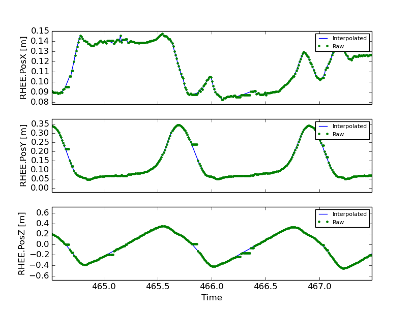
This shows how to compare the raw marker data with the new interpolated data, in this case a simple linear interpolation.
import pandas
import maplotlib.pyplot as plt

data = DFlowData('mocap-module-01.txt', 'record-module-01.txt')
data.clean_data()

unclean = pandas.read_csv('mocap-module-01.txt', delimiter='\t')

fig, axes = plt.subplots(3, 1, sharex=True)

for i, label in enumerate(['RHEE.PosX', 'RHEE.PosY', 'RHEE.PosZ']):

   axes[i].plot(data.data['TimeStamp'], data.data[label],
                unclean['TimeStamp'], unclean[label], '.')

   axes[i].set_ylabel(label + ' [m]')

   axes[i].legend(['Interpolated', 'Raw'], fontsize=8)

axes[2].set_xlabel('Time')

fig.show()